
Description
The MCP23017 module provides a 16-bit general purpose bidirectional I/O port using the I2C bus.
KEY FEATURES OF MCP23017 MODULE:
- 16 bidirectional I/O lines
- I2C bus operates up to 1.7MHz
- 3 address lines for up to 8 devices on same I2C bus
- 2 configurable interrupt outputs
- 25mA per pin / 150mA per package current capability
- 3.3 or 5V operation
It’s not unusual to run out of I/O pins on a microcontroller and the MCP23017 is a popular way to increase the number of GPIO available and has good library support.
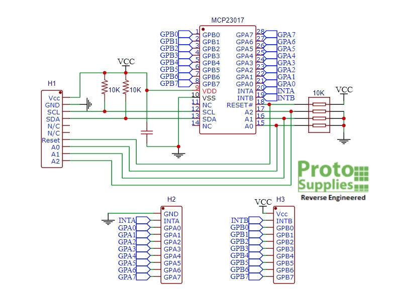
This module brings all of the pins of the MCP23017 chip out to header pins. It also includes 10K pull-up resistors on the I2C SDA and SCK lines, 10K pull-up resistor on the RESET line and 10K pull-down resistors on the address lines..
I2C Bus
Since it interfaces using the I2C bus, the MCP23017 module uses only 2 pins on the MCU and up to 8 modules can be operated off the same I2C bus for a total of up to 128 I/O lines. The I2C SDA and SCK lines have built-in pull-up 10K resistors.
Three address pins (A0-A2) are used for setting the I2C address of the chip. The module has all three pins pulled to ground through 10K resistors giving the base address of 0x20 and can go up to 0x27 if they are all tied to Vcc. If more than one module is used on an I2C bus, each must be set to a unique address.
The I2C bus can operate at up to 1.7MHz for fast manipulation of the I/O lines for higher speed applications. Note that to achieve 1.7MHz operation, Vcc needs to be 5V. When operating at 3.3V the maximum speed is limited to 400kHz which can still handle most I/O requirements.
I/O Ports
The 16 GPIO lines are configured as two 8-bit ports (PORTA and PORTB). Each pin can also be individually defined as an input or output for complete flexibility.
When pins are configured as inputs, an internal 100K pullup resistor can be enabled which is handy for inputs such as switches that require a pullup to Vcc when the switch is open and pull to ground when pressed. This removes the need to add external pullup resistors in some applications.
Another nice feature is that the input pins can be selectively inverted. For instance, a button press that would normally return a logic LOW can be inverted so it returns a HIGH.
Each GPIO pin can handle up to 25mA, but the total current for all pins must be kept under 150mA. If driving something like 16 LEDs, each LED current needs to be kept down around 9mA if they may all be on at the same time to avoid overheating the chip.
Interrupts
Interrupt capability is a nice feature since the MCU does not have to continuously poll the device looking for any change on the inputs.
Each of the two ports has a configurable interrupt output that can be used independently or the two interrupts can work together. Input pins can be set to interrupt the MCU upon a state change.
Another nice feature is that the interrupt outputs can be configurated as active LOW, active HIGH or OPEN-DRAIN.
Reset
The reset pin is active LOW and is pulled up to Vcc using a 10K resistor on the module. It can be be put under MCU control by connecting it to a digital output pin on the MCU. The pin is normally HIGH and momentarily driven LOW to reset the MCP23017.
Assembling The Module
The module ships with 3 strips of male headers for maximum flexibility. The headers can be mounted to the top or bottom of the board or a combination of both.
Since the module has the pins labeled on the bottom side, for solderless breadboard use it is easiest to use the board upside down so the labeling is facing up and visible when making connections.
The way we like to use the module is to solder the single row of header pins used for the MCU control signals to the top (IC side of the board) so that it can be inserted into a breadboard to hold it in position and make male jumper connections to the MCU. The two headers for the I/O ports can be soldered to the bottom of the board (which is now the top) and connections made using female to male jumpers.
Our Evaluation Results:
These parts are very easy to use and have good library support on most MCU platforms.
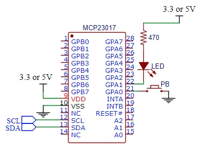
The simple example shown here sets up one pin (A0) as an input to detect a button press. A second pin (A1) is setup as an output to light an LED while the button is being pressed.
Hookup of the module is straight forward.
- Vcc – Connect to 3.3V or 5V to match the MCU
- GND – Connect to ground
- SCL – Connect to I2C SCL on MCU
- SDA – Connect to I2C SDA on MCU
- A0- Connect one side of pushbutton, other side goes to ground
- A1 – Connect to LED cathode. Anode of the LED connects to Vcc through 220 to 470 ohm current limit resistor
The schematic to the right shows the basic setup as viewed from the chip perspective.
PACKAGE INCLUDES:
- MCP23017 16-bit I/O Expander module with I2C bus


Reviews
There are no reviews yet.